Alphabetical Index
Chemical Composition of Steels
Keyword Search
Steel Names
Alloyed Steels
Carbon Steels
Cast Irons
Chromium Steels
Cold Work Tool Steels
Creep Resistant Steels
Hot Work Tool Steels
Molybdenum Steels
PM steels
Stainless Steels
Structural Steels
Tool Steels
Vanadium Steels
White Cast Irons
M2C Carbides
M3C Carbides
M7C3 Carbides
M23C6 Carbides
MC Carbides
Light Microscopy
EDS/WDS Microanalysis
Scanning Electron Microscopy
Transmission Electron Microscopy
X-Ray Diffraction
Help
Contact Us
Home
Carbides in 1.2379 and UNIVERSAL steels (Acoustic Emission Test)
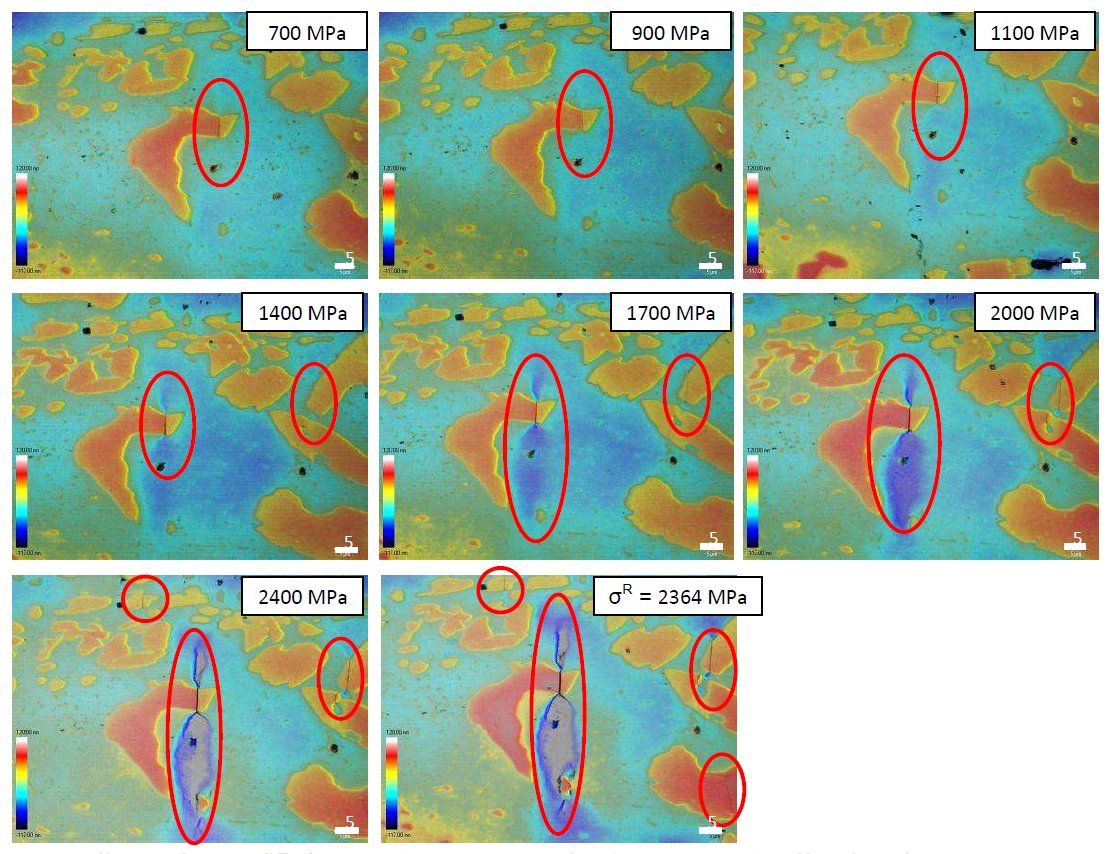
Figure 1: Tensile surfaces of DIN 1.2379 during the loading and unloading bending test. In this case,
the first broken carbides apperas at 700 MPa; plastic deformation in the matrix around the carbide
crack from 900-1000 MPa, it is increasing the deformed area and its depth. From 2000 MPa, the
crack is generated in the the deformed matrix and propagates up to the final break of the
specimen. Also it is possible to see like as it increases the load, they are breaking the carbides of
around. The values of load associated with every phenomenon are stadistics since they depend on
every carbide and its distribution with regard to the rest. Scale bars: 5 µm.
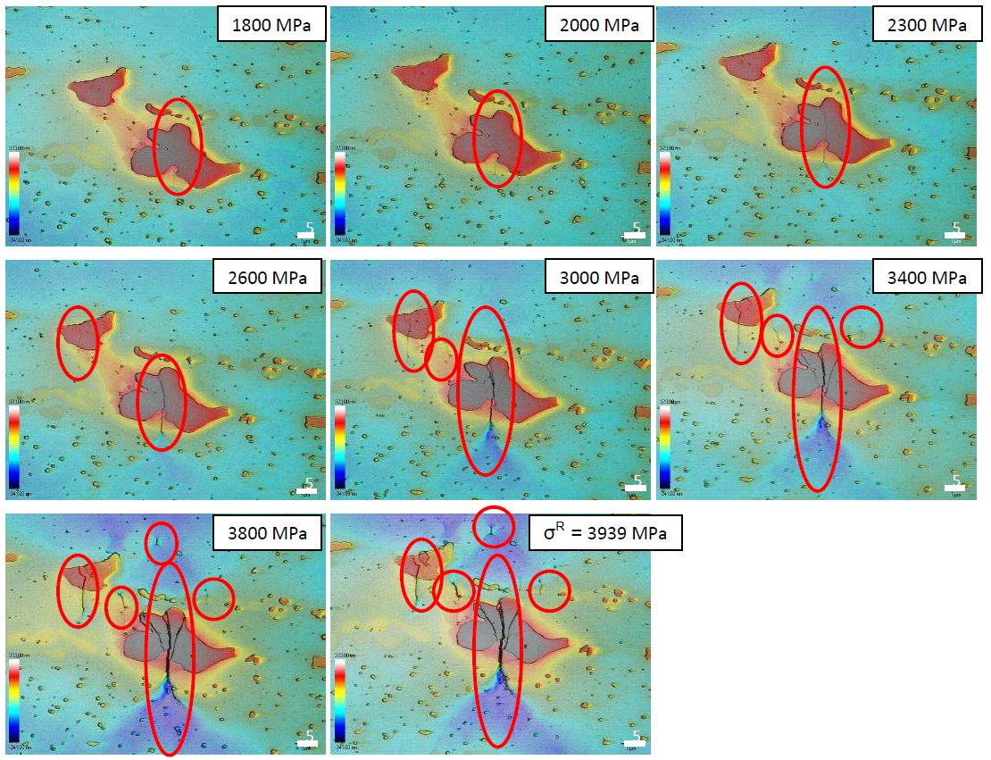
Figure 2: Tensile surfaces of UNIVERSAL during the loading and unloading bending test. In this
case, the first broken carbides apperas at 1800 MPa; plastic deformation in the matrix around the
carbide crack from 2000-2300 MPa, it is increasing the deformed area and its depth. From 3000
MPa, the crack is generated in the the deformed matrix and propagates up to the final break of the
specimen. Also it is possible to see like as it increases the load, they are breaking the carbides of
around. The values of load associated with every phenomenon are stadistics since they depend on
every carbide and its distribution with regard to the rest. Scale bars: 5 µm.
Carbide name: No data
Record No.: 740
Carbide formula: No data
Carbide type: No data
Carbide composition in weight %: No data
Image type: LM
Steel name: 1.2379, UNIVERSAL
Mat.No. (Wr.Nr.) designation: 1.2379
DIN designation: No data
AISI/SAE/ASTM designation: AISI D2
Other designation: No data
Steel group: Tool steels
Steel composition in weight %: No data
Heat treatment/condition: See the text bellow
Note: The usage of advanced high strength steels (AHSS) in structural automotive components has
been broadened in the past few years to satisfy the strict specifications of the automotive industry.
Besides showing excellent strength to weight rations, AHSS have several limitations due to the
high loads required in cold forming and cutting tools, which decrease considerably the tooling
performances. Therefore, these important forces of impact provoke unforeseen breakage of the
dies.
The aim of this research is to study the micromechanical behaviour and fracture mechanisms
(nucleation and crack propagation) during fracture of tool steels using the acoustic emission (EA)
technique. To do that, bending testing specimens of different tool steels were monitored in order
to establish a relationship between AE signals and their mechanical behavior (carbide breakage,
cracks emanating from them and crack propagation through the metallic matrix).
Two commercially available tool steels were selected: a DIN 1.2379 (equivalent to AISI D2)
and a tool steel named as UNIVERSAL (developed by ROVALMA). Details of the chemical
composition and heat treatments of both steels can be found in reference. The 1.2379 tool steel ,
is characterised by a ledeburitic microstructure with grid precipitation of primary carbides during
solidification, formed mostly by the eutectic reaction gamma + M7C3. In UNIVERSAL steel, two
types of primary carbides are present, one type M7C3 but with higher Vanadium and Tungsten
than those found in 1.2379 and a second type of primary carbide of increased hardness and
toughness, rich in Vanadium of the MC type. Carbides in the 1.2379 present an elongated shape,
forming carbide bands along the forging direction, meanwhile primary carbides of UNIVERSAL
steels are more equiaxed and homogeneously distributed in the microstructure.
Prismatic specimens were cut from forged billets, with dimensions 50x4x3 mm with the
longitudinal axis parallel to the forging direction. The obtained samples were then heat treated by
quenching in oil and tempering up to a hardness of 60 - 61 HRC (heat treatments schedule can be
found in reference.
Monitorized AE flexion test: A three point bending test was used to evaluate the mechanical behaviour of the specimens.
The test was carried out in a universal testing machine. The side of the specimens under tension
was ground and polished. Specimen edges were rounder in order to avoid stress concentration
effects. The load rate was fixed at 1 mm/s in all the cases and carried out in air at room
temperature.
Two small magnetic AE sensors are put alongside the specimens in order to detect the AE
signals. The sensors are of the resonance type with a fixed resonance frequency of 700 kHz
(VS700D, Vallen System Gmbh). Two pre-amplifiers with a gain 34dB of the same brand were used (EAP4). The signals were recorded and analysed using the de Vallen System Gmbh AMSY5
analyser. During the measurements, digital filters of 95-850 kHz were applied.
Test procedure: Various complete bending test runs are carried out in order to define the pattern of AE signals
and to determine the specimen´s behaviour. Afterwards, the test runs were paused upon
significant changes in the AE signals. After pausing the test, the surface that had been submitted
to tensile loading, was examined by optical and confocal microscopy to identify the
microstructural features responsible for the possible AE sources. The tests were performed at a
maximum of 70% of the fracture strength (2.100 MPa for the DIN 1.2379 and 2.800 MPa for the
UNIVERSAL steel) to prevent sensor damage due to a sudden sample break.
It can be observed that both materials show a similar behavioural pattern as to the captured AE signals. There are three different zones:
First zone: During the first stage of the test, AE signals are almost inexistent. The reason for this is that
the material is under elastic deformation. Neither the carbides, nor the matrix show effects of
fracture, propagation or plastic deformation that generate AE signals. In other words, linear
behaviour of the material is associated with the absence of AE signals, once background noise is
filtered out.
Some isolated AE signals appear which are suspected to be caused by premature fracture of
carbides or a chip off of the material due to the polishing; however there is no certainty at this
point.
Second zone: The first AE signals appear in the DIN1.2379 at approximately 11 s and in the UNIVERSAL
at 27 s (that correspond to a deformation of 0,4 % and 1% respectively). The signals increase
gradually in intensity and abruptly in number. During this stage in both materials in the various
micrographics, broken carbides can be discerned. As shown in figure 1, the amount of broken
carbides increases considerably with the rising stress. In some cases a small area of plastic
deformation appears.
Third zone: Both the amounts of registered signals as well as the accumulated energy increase
considerably. The intensity does not increase; moreover the average value decreases slightly. At
this stress level nearly all carbides at the surface have been fractured, more areas have plastic
deformation and even small matrix cracks appear. At this point, the test has been stopped to
prevent the specimens from breaking down all together but it is expected that until its final
breakdown, the fractures will increase until the broken carbides connect and the specimen breaks
in two.
The stress level at which carbides start breaking in the DIN 1.23679 steel is 640 MPa, which is
20% of the fracture strength of this material. In the case of the UNIVERSAL steel, signals that
point out the breaking of carbides start appearing at 1700 MPa which corresponds to
approximately 45% of the fracture strength. Such results can be explained by the lower fracture
toughness of primary carbides in the 1.2379, as has been previously evaluated by nanoindentation.
Links: No data
Reference: Not shown in this demo version.