Alphabetical Index
Browse by Elements
Keyword Search
Dry Etchants
Dry and Wet Etchants
Wet Etchants
Bulk Etchants
Layer Etchants
Nano Etchants
Single Crystal Etchants
Thin Film Etchants
Thin Foil Etchants
Wafer Etchants
Al Etchants
Cd Etchants
Ga Etchants
Ge Etchants
In Etchants
New Etchants
Other Etchants
Si Etchants
Zn Etchants
Help
Home
Micromachined Wagon-Wheel Pattern - Silicon - Wet Etching
Material Name: Silicon
Recipe No.: 10316
Primary Chemical Element in Material: Si
Sample Type: Wafer
Uses: Etching
Etchant Name: None
Etching Method: Wet etching
Etchant (Electrolyte) Composition: Sample preparation: Prior to the etch experiments, all samples were cleaned in 65% HNO3 (Merck GR for analysis)
followed by deionised water (Millipore, 18 M OHm.cm) in order to remove contaminants.
Samples with an aluminium back contact were protected to prevent damage to the metal
layer due to cleaning by keeping the sample within the sample holder. For the other samples,
an ohmic contact was made after cleaning by applying GaIn (Sigma Aldrich 99.99%+
GaIn eutectic) to the back after locally removing some of the native oxide or SiRN by
scratching the back surface with a diamond tip pen. All etching experiments were done
in a 5.0 mol/l KOH solution (prepared from Merck Selectipure pellets) at a temperature
of 50 C in the dark. Prior to and during the experiments the solution was constantly
bubbled with argon to remove dissolved oxygen. This, together with the hydrogen formation
at the surface, caused convective mixing of the etching solution. Native oxide was removed using the KOH etching solution itself and was monitored by measuring the
OCP. A fixed potential was applied after the native oxide was removed. These potentials
varied from -1500 mV to -875 mV vs. SCE. The etch time for the wagon-wheel pattern
was 60 min and for the offset trench pattern 180 min. After etching the samples were
briefly quenched in a diluted HNO3 solution to stop the etching processes and remove KOH residues.
Experimental Setup: To evaluate the cation/electrochemistry combined effect on (111) step anisotropy, etch experiments
using hemispherical shaped samples have been performed under electrochemical
controlled conditions. The oxidation state of both the types of surface steps was controlled
by externally applying a constant electrical potential. The specific potentials were chosen
using the results obtained from wagon-wheel pattern experiments. To isolate
the effect of TMA+ cation, a mixture of TMAH (Chameleon Reagents for electronics
25%) and KOH (Chameleon Reagents for electronics 85%) in deionised water (Millipore, 1 8M Ohm.cm) was used. The concentration of TMA+ cation can then be controlled without
influencing the pH of the system. The kinematic wave theory was used to express the
measured etch rate data in terms of microscopic properties such as step/kink velocity,
terrace and step roughening. The OH- concentration used for all experiments was 5.0
mol/l. Three TMA+ concentrations were used for the experiment, which were 0.0, 0.5 and 1.0 mol/l.
All experiments were performed at the Micromachining and MEMS lab at Nagoya
University in Japan, where both the polished hemispherical samples and analysis equipment
were available. The samples were p-type normal-doped (110) oriented samples with a diameter of 40 mm. A 1 µm thick SiO2 mask was created on the bottom and the
orientation flats of the samples using wet oxidation at 800.C. The silicon oxide was removed
from the spherical surface using a 1% HF solution while the wafer flats and bottom
were protected by photoresist and resist foil respectively. Prior to etching, the samples
were cleaned in concentrated H2SO4 (Hagashi pure chemical 99.8%) at 80.C for 30 min,
followed by deionised water for an additional 30 min. An ohmic contact between the Si
and a gold connection pen was achieved by locally removing the SiO2 using a diamond
tip pen and applying GaIn eutectic (Sigma Aldrich 99.99%+ GaIn eutectic). The sample
was mounted in a KelF sample holder and the electrical contact was protected from the
solution using Teflon coated Viton and silicone O-rings. The sample was held in place
by three KelF rods positioned in a radial pattern around the sphere. The etch setup
consisted of a standard electrochemical cell with a platinum plate electrode (Radiometer
M24Pt) acting as a counter electrode. As a reference electrode, a standard calomel electrode
(SCE, Radiometer REF401) was used. The etch vessel itself was made from Teflon
and was partly submerged in a water bath at a constant temperature. The etchant solution
was constantly bubbled with Argon gas prior and during the etching experiment to
remove dissolved oxygen. External electrical potentials were applied using a potentiostat
(PalmSens). Current and potential were monitored using the same potentiostat. The etch
time for all experiments was 4 hours. This etch time will result in a etch depths smaller
than of 150 µm. The experiments were performed at a constant temperature of 50 C in
the dark. After etching, the samples were quenched in diluted H2SO4 to stop the etch
process and remove KOH residue. The four (set point) potentials chosen were (vs SCE):
• -1500 mV: Close to the OCP of the actual sample and of bulk (100) and (110) surfaces.
• -1250 mV: Close to the OCP of bulk (111) surfaces.
• -1000 mV: Close to the oxidation peak potential of both (100).
• -750 mV: slightly past the passivation potential[110].
Due to the potential drop over the radius of the sphere, the actual potential of the Si
surface does not necessarily correspond to the set point. The surface potential is then
dependent on the exposed surface and the anodic current through the sample. The anodic
current is in turn dependent on the applied potential and the electrochemical oxidation
rate. As the rate of electrochemical oxidation can change during the etch experiments
due to the evolving silicon surface, the actual surface potential can drift. If the surface
potential drifts to a very positive value (close to the passivation potential), passivation
occurs, creating an oxide layer on the exposed Si surface. Due to the etchant composition
(KOH + TMAH) this oxide is etched away very slowly, disrupting the etch experiment.
These issues make it difficult to both determine and predict the actual surface potential.
The final surface potential was calculated after completion of the etch experiments from
the measured currents.
Anisotropic etch rates were determined by measuring the local etch depth using a
tactile coordinate measuring machine (Zeiss UMPC 850 Carat) which contains a 1 mm
diameter spherical sapphire tip and uses a contact force of 0.1 N. The total measured range spans 70 deg. from the top of the sphere with a spacing of 2 deg. The center point of
the hemisphere was determined by measuring the protected bottom and alignment flats.
Procedure (Condition): No data
Note: No data
Reference: Quoc Duy Nguyen, Electrochemistry in anisotropic etching of
silicon in alkaline solutions: A kinematic wave analysis, PhD Thesis, Transducers Science and Technology
Group of the MESA+ Research Institute at the University of Twente, Enschede, Netherlands, 2007, pp. 46-52, 96-98.
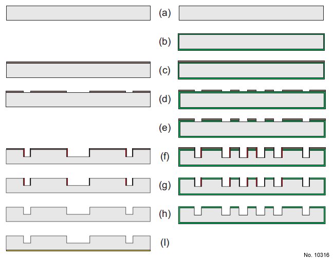
Figure 1: Outline of the fabrication process of both the wagon-wheel patterns (left side)
and the rectangle offset pattern (right side). The individual steps are indicated. Process
starts with a (110) substrate for the rectangle offset pattern and a (110) or (100) substrate
for the wagon-wheel pattern. (b) Depositing SiRN using LPCVD. (c) and (d) standard
lithography using photoresist. (e) resist pattern to SiRN layer using reactive ion etching.
(f ) Deep etching using Bosch process using photoresist as mask material. (g) Removal of
photoresist. (h) Removal of fluorocarbon deposits. (i) Creating aluminium back contact
using sputtering.
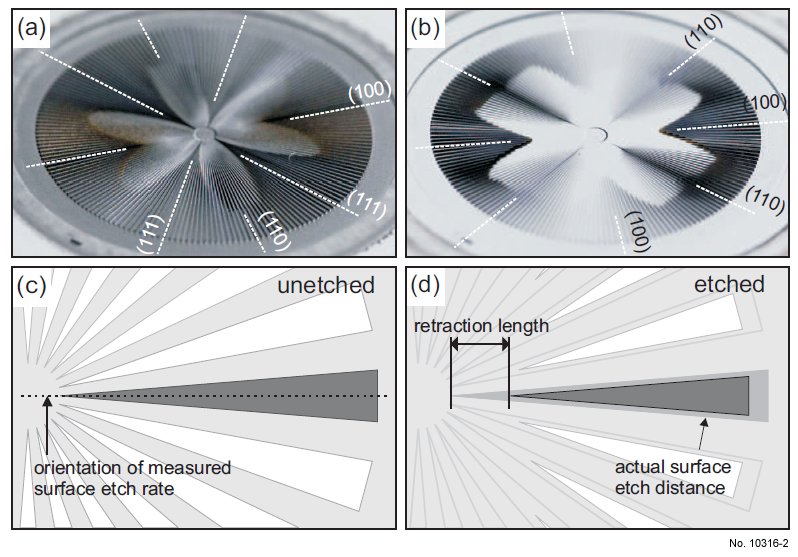
Figure 1: Outline of micromachined wagon-wheel pattern. Top two pictures show an
etched wagon wheel on a (110) (a) and (100) substrate(b), the major orientations are indicated. Diagrams (c) and (d) show the principle of the wagon-wheel pattern including the
relative difference in size of the retraction length as compared to the actual perpendicular
surface etch distance.