Alphabetical Index
Browse by Elements
Keyword Search
Dry Etchants
Dry and Wet Etchants
Wet Etchants
Bulk Etchants
Layer Etchants
Nano Etchants
Single Crystal Etchants
Thin Film Etchants
Thin Foil Etchants
Wafer Etchants
Al Etchants
Cd Etchants
Ga Etchants
Ge Etchants
In Etchants
New Etchants
Other Etchants
Si Etchants
Zn Etchants
Help
Home
X-Cut Alpha Quartz - Dry Etching
Material Name: X-cut alpha quartz
Recipe No.: 10331
Primary Chemical Element in Material: Si
Sample Type: Wafer
Uses: Etching
Etchant Name: None
Etching Method: Dry etching
Etchant (Electrolyte) Composition: Experiments were performed using an STS320 RIE system
employing a liquid cooling system. The chamber pressure was
fixed at 20 mTorr, and the RF power was fixed at 300W5. This
led to a bias voltage which ranged from 650 to 700 V. The
target and the bottom plate were held at 15 C.
Etch targets were polished x-cut single crystal quartz
wafers provided by LapTech Precision and (where mentioned)
polished fused silica (amorphous SiO2) wafers provided by
Valley Design. All targets were segments of 1" discs or smaller
samples cleaved from 1" discs. Shadow masks for the argonconcentration
trials were 500 µm thick fused quartz wafers
with 8 mm by 2 cm central rectangular windows. Shadow
masks for the mask effect trials were 1 cm by 3 cm plates
0.3 to 1 mm thick made of fused silica, alumina, or Ni with
4mmdiameter holes through their centers. Etching gases were
SF6 and Ar, with total gas flow rate fixed at 18.3 sccm. All gas
percentages are in volume %.
Prior to etching, debris was removed from the surface of
thewaferswith a dry nitrogen gun, and all etch runs beganwith
a 5 min oxygen plasma clean (50 WRIE power, 300 mTorr of
chamber pressure) to remove residual organic contaminants.
In the mask effect trials, wafers were etched in individual
runs for 5.5 h with either no mask or one of the three possible
shadow masks using both 100% SF6 and 87.5% Ar (i.e.
12.5% SF6 by volume). Etch depth and surface roughness
were measured using both a contact and optical profilometer
(ZYGO New View). SEM images and energy-dispersive x-ray
spectroscopy (EDS) spectra were obtained with a JEOL-7000F
in secondary electron mode.
Wafers masked only by quartz were etched at several ratios
of SF6 to Ar to study the effects of the Ar concentration on
the etch rate and long-etch-time pitting. At 0%, 50%, 75%,
and 87.5% Ar these etches were carried out for much longer
times to obtain membranes of less than 20 ìmthickness. Long
etches with 50% Ar were also conducted on fused silica to
study the dependence of the pitting and etch rate on crystalline
microstructure, and conducted on x-cut quartz masked by Ni
to study the long-etch stability of this mask.
Procedure (Condition): No data
Note: In this paper we investigate the effect of Ar concentration and shadow mask material on the
etch rate, surface roughness, and micromask pit density and depth for reactive ion etching
(RIE) of x-cut alpha quartz. The ratio of SF6 to Ar is varied at constant power and pressure to
find an optimum Ar concentration for thinning x-cut quartz while maintaining good surface
quality. The recipe is used with an STS320 RIE system to produce smooth, through-hole-free,
insulating quartz membranes of 7 ìm thickness in selective locations on 100 ìm thick x-cut
quartz wafers. We demonstrate that surface quality is much improved by replacing at least
75% of the SF6 by volume with Ar, and that for non-inductively coupled plasma RIE the
standard mask material nickel is detrimental to surface quality for long etch times.
Reference: M D Minnick, et al., Optimum reactive ion etching of x-cut
quartz using SF6 and Ar, J. Micromech. Microeng. 23 (2013), pp. 1-7.
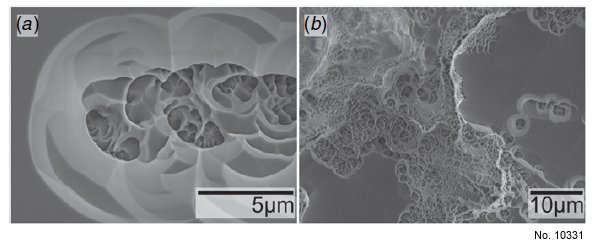
Figure 2: Deep pitting in quartz etched using 0% Ar (SF6 only) after
only 5.5 h (26.5 µm etch depth), (a) near the center and (b) near the
edge of the etch mask.
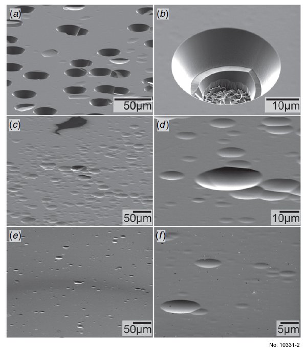
Figure 3: Reduced pitting after long etch times with increasing
Ar%: (a), (b) 50% Ar, 21.25 h (c), (d) 75% Ar, 29.73 h,
(e), ( f ) 87.5% Ar, 33 h. With 50% Ar, pit depth increases with etch
time and breaks through the thin membrane resonator as shown in
(b) (72.2 µm etched out of a 100 m wafer). 75% or more Ar did
not show a pit depth increase as the etch progressed and 87.5% Ar
showed even lower pit depth and density.
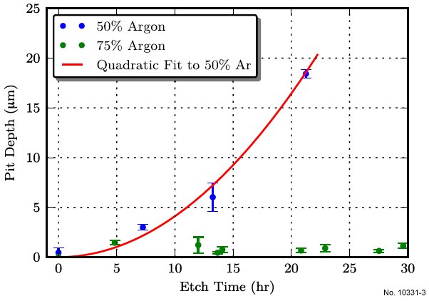
Figure 4: Pit depth versus etch time for 50% and 75% Ar. This plot
illustrates that pit depth increased as the etch progressed for 50% Ar,
but not for 75% Ar.
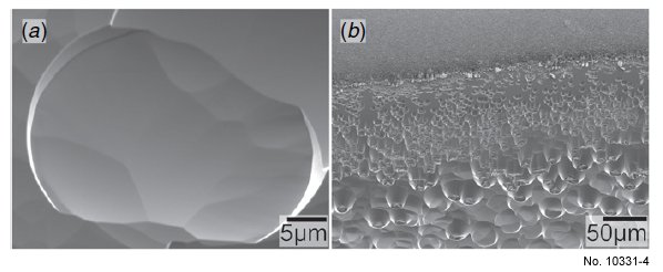
Figure 5: Results of etching fused silica with 50% Ar (50% SF6) for
21.25 h, depth of 97.4 µm, (a) typical center pit and (b) increased
pitting near the edge of the shadow mask. The smoother angles
observed, especially at the bottom of the pits, supports the
hypothesis that the crystal direction dependence of the etch rate is
responsible for the sharp-angle pitting when etching x-cut quartz.
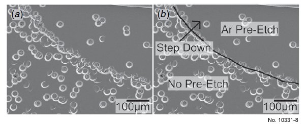
Figure 6: Reduced (but not eliminated) pitting from an extra Ar
pre-etch and a quartz ridge transformed into a curve of
densely-packed pitting, (a) clear and (b) annotated.
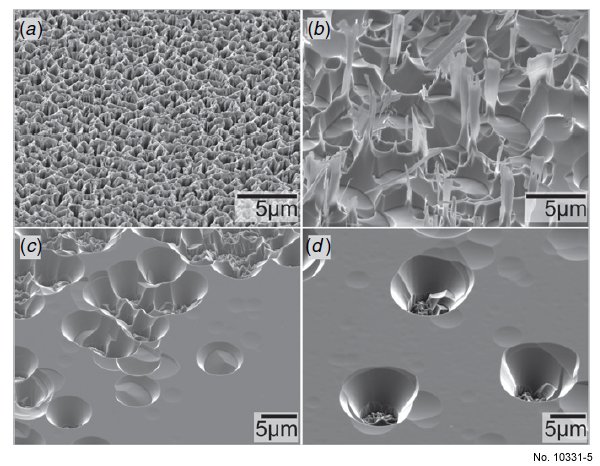
Figure 8: Surface of x-cut quartz after etching for 5.5 h with 100%
SF6 while shadow masked with (a) alumina, (b) Ni, (c) fused silica,
and (d) no mask. The quartz surface is not only etched far more
slowly with alumina as the shadow mask, but also greatly damaged.
Ni masking gave more pitting than silica masking and left residue
on the surface. Pitting with fused silica masking is similar to no
masking.
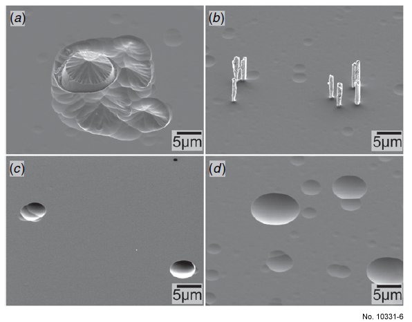
Figure 9: Surface of x-cut quartz after etching for 5.5 h with
87.5% Ar while shadow masked with (a) alumina, (b) Ni, (c) fused
silica, and (d) no mask. The shadow masking material has a much
smaller effect on surface quality when Ar is present in the etch gas.
The surface damage with an alumina mask is greatly reduced by the
introduction of Ar gas. Initial pitting is similar for Ni and quartz
masks but surface damage is still present for non-quartz masking. Ni
masking resulted in hollow column-shaped surface structures.
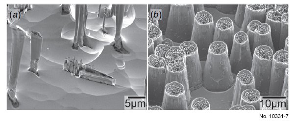
Figure 10: Structures observed on the surface for deep etching x-cut
quartz with Ni shadow masking using (a) 87.5% Ar and
(b) 93.75% Ar. Lowering the SF6 concentration reduces the lateral
etch rate and changes the structures from (a) hollow pillars to
(b) conical-shaped structures.br>