Alphabetical Index
Browse by Elements
Keyword Search
Dry Etchants
Dry and Wet Etchants
Wet Etchants
Bulk Etchants
Layer Etchants
Nano Etchants
Single Crystal Etchants
Thin Film Etchants
Thin Foil Etchants
Wafer Etchants
Al Etchants
Cd Etchants
Ga Etchants
Ge Etchants
In Etchants
New Etchants
Other Etchants
Si Etchants
Zn Etchants
Help
Home
PDMS - Dry Etching
Material Name: PDMS
Recipe No.: 10352
Primary Chemical Element in Material: No data
Sample Type: Layer
Uses: Etching
Etchant Name: None
Etching Method: Dry etching
Etchant (Electrolyte) Composition: The PDMS used throughout the study was Sylgard 184
from Dow Corning Corp, Midland, MI. The elastomer was
mixed in a 10:1 ratio with its curing agent and then placed in
a desiccator for at least 45 min to remove the bubbles created
during mixing. Samples were then made by either spinning
the polymer on precleaned glass slides and curing at 90 °C,
or by pouring it into plastic weighing dishes and curing at low heat.
The wet etch experiments were performed using a solution
of tetrabutylammonium fluoride (C16H36FN) in
n-methyl-2-pyrrolidinone (C5H9NO), 3:1 (v/v) NMP:TBAF,
both supplied by Sigma-Aldrich. The surface of the PDMS
was first coated with copper or aluminum either by sputtering
or electron-beam evaporation. Rectangular windows
were then etched in the metal masking layer using standard
photolithographic processing and wet etching. The PDMS
was then immersed in the solution and gently agitated during
the etch. Agitation was required due to the relatively slow
etch rate, and the need to replace etchant at the surface, as is
commonly done in the laminar flow etch process described
by Takayama et al.3 The substrates were periodically removed
from the etchant, rinsed with isopropanol and water,
dried with nitrogen, and examined under the microscope in
order to monitor the etch progress. Results of this approach
are shown in Fig. 3 and discussed in the following section.
Dry etching experiments were performed in an Oxford
Plasma Technology mP 80 parallel plate reactor equipped for
reactive ion etching. Oxygen (O2) and tetrafluoromethane
(CF4) gases were supplied by Messer, MG Industries, Malvern,
PA. All samples used for etch rate determination were
etched for 60 min while the CF4/O2 ratio, total gas pressure,
and RF power were varied (see Table 1). The surface of each
sample was partially masked with Kapton tape prior to etching
in order to create a distinct step feature that could be
measured using a Dektak 3030 stylus profilometer. The step
height was also measured using a Leitz Ergolux optical microscope
with a calibrated reticle. Each sample was cross
sectioned and laid flat on a microscope slide to obtain a side
view of the etch profile. Several cross sections were taken for
each sample and the average step-height value was used.
Procedure (Condition): No data
Note: A fluorine-based reactive ion etch (RIE) process has been developed to anisotropically dry etch the
silicone elastomer polydimethylsiloxane (PDMS). This technique complements the standard
molding procedure that makes use of forms made of thick SU-8 photoresist to produce features in
the PDMS. Total gas pressure and the ratio of O2 to CF4 were varied to optimize etch rate. The RIE
recipe developed in this study uses a 1:3 mixture of O2 to CF4 gas resulting in a highly directional
and stable etch rate of approximately 20 mm per hour. Selective dry etching can be performed
through a photolithographically patterned metal etch mask providing greater precision and
alignment with preexisting molded features. The dry etch process is presented in this article along
with a brief comparison to recently reported wet etch approaches.
Reference: J. Garra, et al., Dry etching of polydimethylsiloxane for microfluidic systems, J. Vac. Sci. Technol. A 20(3), May.Jun 2002, pp. 975-982.
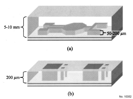
Figure 1: (a) Thick PDMS layer cast in SU-8 mold. The SU-8 features are
patterned in the surface of the PDMS. (b) The PDMS cast in the SU-8 mold
has the same thickness as the SU-8 itself. The mold features extend through
the membrane.
Table 1: Dry etch data for PDMS at varying pressures and gas ratios. All
etches were performed for 60 min.
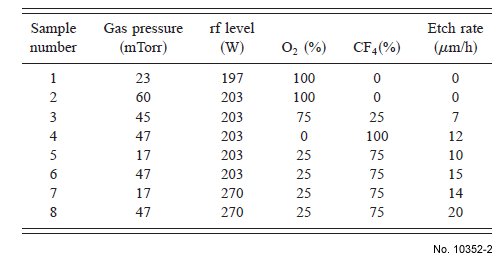
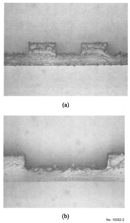
Figure 2: Cross sections of two different structures, (a) and (b), etched in
PDMS as seen under the optical microscope at 203 magnification. The twin
structures in (a) are roughly 140 µm wide and 60 µm high. The rectangular
etch cavity in (b) is 350 mm wide and 60 mm deep. The measurement reticle
is not visible in the pictures.
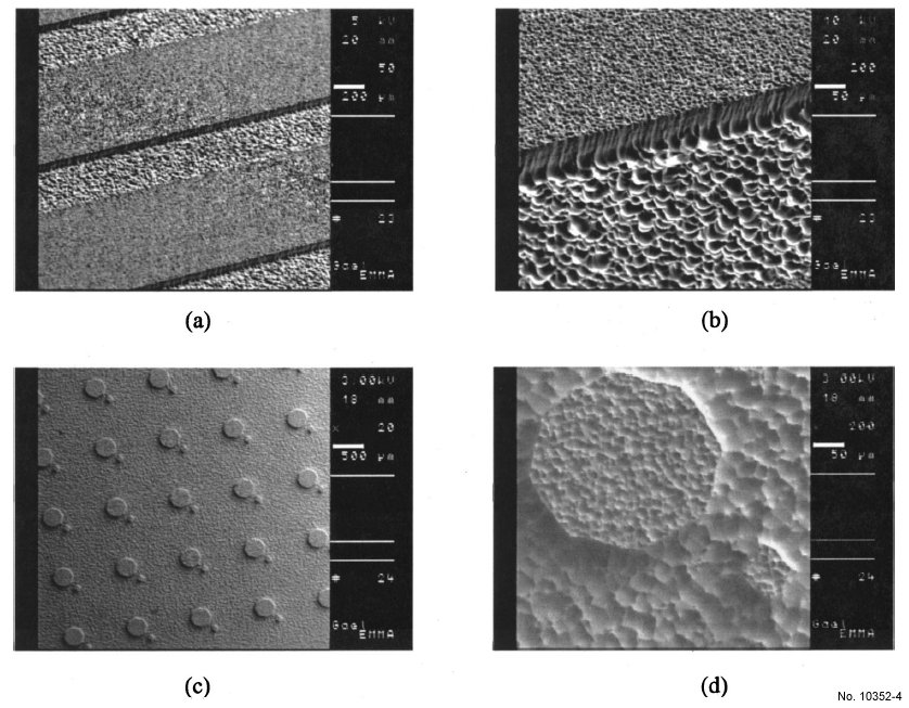
Figure 3: Two different patterns were etched into the PDMS samples through lithographically defined aluminum masking layers to show how dry etching can
be used to bulk micromachine structures in the surface of PDMS. The first structure, shown in (a) and at increased magnification in (b) consists of a series of
parallel channels 350 µm wide and 70 µm deep. The second structure, shown in (c) and again in (d) is an array of octagons (300 µm wide) and rhombuses
(45 µm wide) raised 70 µm from the bottom surface. The micrographs show the roughness characteristic of the etched PDMS surface.