Alphabetical Index
Browse by Elements
Keyword Search
Dry Etchants
Dry and Wet Etchants
Wet Etchants
Bulk Etchants
Layer Etchants
Nano Etchants
Single Crystal Etchants
Thin Film Etchants
Thin Foil Etchants
Wafer Etchants
Al Etchants
Cd Etchants
Ga Etchants
Ge Etchants
In Etchants
New Etchants
Other Etchants
Si Etchants
Zn Etchants
Help
Home
Tungesten - Dry Etching
Material Name: Tungesten
Recipe No.: 10353
Primary Chemical Element in Material: Ti
Sample Type: Layer
Uses: Etching
Etchant Name: None
Etching Method: Dry etching
Etchant (Electrolyte) Composition: Three different etching equipment are used.
1. A Cobrain swafer--Power, at 25 kHz frequency, is applied
at the lower electrode leaving the upper electrode
grounded in the RIE mode, or at the upper electrode leaving
the lower electrode floating in a PE mode.
2. A Tegal HRe-system--Permanent magnets are placed
around the cylindrical wall and above the upper electrode.
The upper electrode is always grounded. It is possible to
apply power at 13.56 MHz at the wall os the reactor (PE
mode) or at the lower electrode (RIE mode).
3. A few experiments were performed using MATRIX 303 equipment--A remote plasma is created in the upper
part of the reactor, while the wafer is placed in the lower
part, on a heated chuck. Both parts of the reactor are divided
by a grid made of aIumina.
Procedure (Condition): No data
Note: No data
Reference: Patrick Verdonck, et al., Analysis of The Etching Mechanisms of Tungsten in
Fluorine Containing Plasmas, J. Electrochem. Soc., Vol. 142, No. 6, June 1995, pp. 1971-1976.
Table 1: Tungsten etch rates, uniformities, and selectivities
toward resist as a function of pressure and power
in the SWAFER reactor in RIE mode.
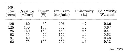
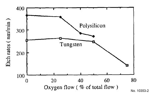
Figure 1: Tungsten and polysilicon etch rates as a function of oxygen
flow, for NF3-O2 plasmas in the RIE mode, at 150 mTorr pressure, and
50 W power in the SWAFER reactor.
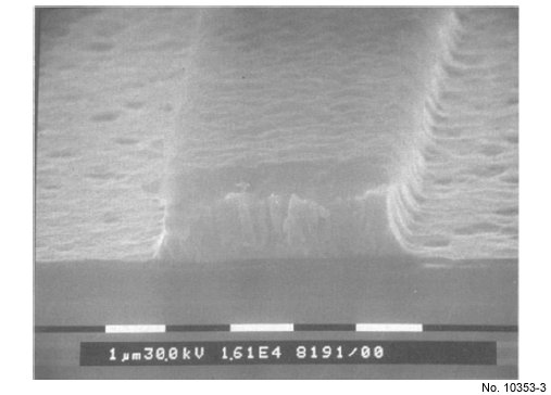
Figure 2: Tungsten profile after RIE etching with a pure NF3 plasma
using a PECVD oxide mask.
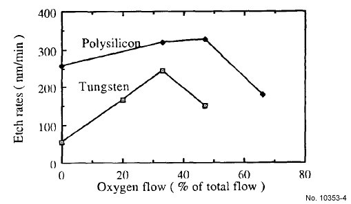
Figure 3: Tungsten and polysilicon etch rates as a function of oxygen
flow, for NF3-02 plasmas in PE mode, at 150 mTorr pressure and
50 W power in the SWAFER reactor.
Table 2: Tungsten etch rates and uniformities as a function
of power in the SWAFER reactor in PE mode.
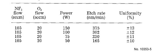
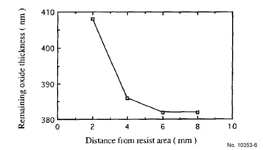
Figure 5: Remaining PECVD oxide thickness as a function of distance
from a large resist area after a PE mode etching with a NF3-O2
plasma in the SWAFER reactor.
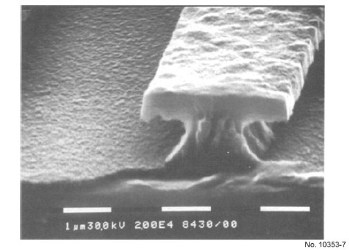
Figure 6: Tungsten profile after PE mode etching with a NF3-O2
plasma, using a PECVD oxide mask.
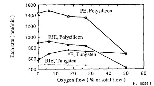
Figure 7: Tungsten and polysilicon etch rates as a function of oxygen
flow and etching mode. Total flow, 96 sccm: pressure, 10 mTorr:
power, 400 W in the TEGAL HRe-reactor.
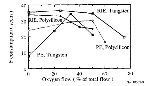
Figure 8: Fluorine consumption for tungsten and polysilicon etch processes
as a function of oxygen flow and etching mode in the SWAFER.
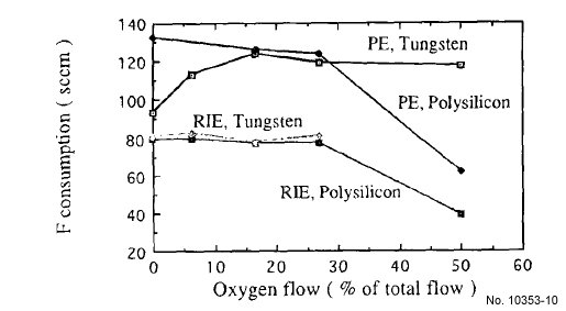
Figure 9: Fluorine consumption for tungsten and polysilicon etch processes
as a function of oxygen flow and etching mode in the Tegal HRe-.