Alphabetical Index
Browse by Elements
Keyword Search
Dry Etchants
Dry and Wet Etchants
Wet Etchants
Bulk Etchants
Layer Etchants
Nano Etchants
Single Crystal Etchants
Thin Film Etchants
Thin Foil Etchants
Wafer Etchants
Al Etchants
Cd Etchants
Ga Etchants
Ge Etchants
In Etchants
New Etchants
Other Etchants
Si Etchants
Zn Etchants
Help
Home
Beta-Ga2O3 - Dry Etching
Material Name: Beta-Ga2O3
Recipe No.: 10362
Primary Chemical Element in Material: Ga
Sample Type: Layer
Uses: Etching
Etchant Name: None
Etching Method: Dry etching
Etchant (Electrolyte) Composition: Dry etching has been extensively used in microelectronic fabrication for its advantages of feature size, tunable etch profile and etch rate over wet etching. In this work, I develop dry etching process using inductively-coupled-plasma reactive-ion etching (ICP-RIE) for Ga2O3 aiming at tunable etch rate, vertical sidewalls and minimized damage.
In this work, we use a BCl3/Ar gas mixture to etch Ga2O3 because BCl3 has been shown to etch Ga2O3 faster than Cl244) and Ar gives an extra flexibility in tuning relative physical and chemical components. We use ICP to create a high-density plasma that is expected to increase the etch rate and yield smoother surface morphologies than pure RIE.44) We adjust different parameters in ICP-RIE etching such as ICP power, RIE power, chamber pressure and BCl3/Ar gas ratio to examine their effects on etch rate, surface morphology and etch profile. Etch rates exceeding ~160 nm/min with nearly-vertical sidewalls and smooth etched surfaces are obtained under the optimal etching conditions.
Experimental details are as follows: 2-in. unintentionally doped (UID; electron concentration ~10 exp(17) cm(-3) Ga2O3 wafers of (-201) surface orientation from Tamura Inc. were diced into 5 x 5 mm2 pieces and cleaned in acetone and isopropanol (IPA) and blown dried with N2. The samples were patterned with AZ S1813 photoresist (PR) using contact photolithography and a mask of various sizes of rectangular strips. The samples were then etched in a Plasma-Therm 770 ICP-RIE system that applies an RF power (ICP power) to a coil to inductively create a high-density plasma and a separate RF power (RIE power) on the chuck to direct the reactive ions to the substrate. To study the effect of each parameter (ICP power, RIE power, chamber pressure and gas ratio), one parameter is varied within a reasonable range while other parameters are kept fixed. The etch rate was measured using a Tencor P-10 surface profilometer. Scanning electron microscopy (SEM) images were then taken at a 79¯ tilt angle to examine etch profiles and atomic force microscopy (AFM) was used to measure the surface roughness.
In the first set of experiments, RIE and ICP powers were varied while keeping the BCl3/Ar gas flows at 35/5 sccm and chamber pressure during etch at 5 mTorr (Fig. 3.1). As shown in Fig. 3.1(a), at high ICP powers (900 W), the etch rate increases significantly with increasing RIE power, indicating that the physical component plays an important role because enhanced ion bombardment can help to remove etch products and simultaneously create surface defects to promote chemical reaction. However, at lower ICP power (350 W), the etch rate stays almost constant with increasing RIE power. This is possibly because at low ICP powers, not many Cl radicals are generated in the plasma and the chemical component is therefore weak. Therefore, an enhanced physical component does not go hand-in-hand with an as-strong chemical one. Moreover, as ICP power increases, the degree to which the etch rate increases with RIE power also increases. At 550 W ICP power, the etch rate increases from 72.6 to 93.5 nm/min (~28% increase) whereas the etch rate increases from 94 to 165 nm/min at 900 W ICP power (~75% increase). For the RIE power of 60 W, the Ga2O3 etch rate increases almost linearly with increasing ICP power as shown in Fig. 3.1(b). This happens because increasing ICP power will generate more reactive species and positive ions in the plasma, which will enhance both chemical and physical components. By using ICP-RIE etching at high ICP powers, we have obtained ~4x enhancement in the etching rates compared to earlier dry etching studies performed on beta-Ga2O3.
After studying the effect of ICP and RIE powers, I studied the effect of the BCl3/Ar gas ratio on Ga2O3 etch rate. Experiments at following BCl3/Ar gas flow rates were carried out: 40/0, 35/5, 25/15, 20/20, 15/20 sccm, keeping the total gas flow rate at 40 sccm. ICP and RIE powers of 900 W and 30 W were used for these studies while keeping the chamber pressure at 5 mTorr. The measured etch rates for different gas flow rates are shown in Fig. 3.2. We find that adding Ar to BCl3 does not change the etch rate significantly till a BCl3/Ar flow rate of 25/15 sccm. Further increase in the Ar flow rate decreases the etch rate. Ar is expected to promote physical etching because Ar+ ions can help remove etch products and creating active sites for chemical etching. If BCl3 only provides chemical component by producing the reactive Cl radical, adding Ar to pure BCl3 would enhance etch rate because of synergic mechanism. A previous study found that BCl3 produces heavy BCl+2 and BCl+3 ions that do physical etching as well.48)Therefore, BCl3 by itself can provide both chemical and physical etch components in the plasma to promote the synergic mechanism. As more Ar is added, the etch rate eventually drops because of the lack of Cl radical. The etch rate in pure Ar was not obtained because the plasma could not be lit at same ICP/RIE powers and pressure. However, following the trend in Fig. 3.2, further reduction in the etch rate is expected for pure Ar. Liang et al. have performed a similar study of Ga2O3 etching with a SF6/Ar mixture that shows a trend similar to Fig. 3.2 and negligible etch rate with pure Ar.
In the last set of experiments, we studied the effect of chamber pressure on (-201) beta-Ga2O3 etch rate while the ICP/RIE powers are kept at 900 W/90 W and BCl3/Ar flow rate at 35/5 sccm. As shown in Fig. 3.3, the etch rate decreases when the chamber pressure increases from 5 to 12 mTorr. At higher pressures, more collisions occur between particles leading to a reduced mean-free path and recombination of free radicals. This enhanced recombination leads to less chemically reactive species and reduced chemical component of etching. Further, the reduced DC bias across the sheath at higher pressures reduces ion bombardment energies and therefore the physical component. Reduction in both physical and chemical components leads to the decrease in etch rate at higher chamber pressures.
The morphology of the sample surface before and after etching is studied using AFM. The RMS roughness is compared across different etching conditions mentioned in previous paragraphs. The effect of increasing RIE power on the RMS roughness is shown in Fig. 3.4(a). With increasing RIE power, the etched surface maintains roughly the same roughness as the unetched surface, suggesting that the etching has caused minimal surface damage. The RMS roughness even decreases slightly as the RIE power increases beyond 60 W, indicating that a balance is reached between the physical and chemical etching components. This reduced RMS at higher RIE is consistent with the enhanced etch rate at higher RIE, both being evidences for synergic mechanism.
Figure 3.4(b) shows the influence of the BCl3/Ar flow rate on sample roughness. When BCl3 flow rate is greater than or equal to Ar flow rate, the RMS roughness does not change much from the unetched sample (RMS: 0.256 nm), indicating synergic etching. However, for BCl3/Ar flow rate of 15/25 sccm, RMS roughness increases drastically to 54.8 nm. This abrupt increase in roughness is probably because there are not enough Cl radicals in this condition to do chemical etching and the physical and chemical etch components go out of balance. Pure BCl3 results in an RMS as good as the mixture of BCl3 and Ar, confirming that BCl3 provides BCl+2 and BCl+3 ions that also perform physical etching. This is consistent with the etch rate data shown in Fig. 2.2 that shows that pure BCl3 etches as fast as BCl3/Ar mixture.
The RMS roughness increases only slightly with increase of chamber pressure as shown in Fig. 3.4(c), suggesting that synergic etch mechanism is maintained in the 5 -12 mTorr chamber pressure range. From these studies, we identify a large window of ICP-RIE etching conditions under which very smooth surface morphologies with sub 1 nm RMS roughness for 5x5šm2 scans can be obtained. This finding will be crucial for device fabrication, if can be combined with sharp etched sidewalls.
SEM images were taken at a tilt angle of 79¯ to examine the etch profile and sidewalls of the (-201) beta-Ga2O3 under all etch conditions. Smooth and nearly vertical sidewalls were obtained for the samples etched under the synergic mechanism. Figure 3.5 shows the SEM image of the sample etched at 350 W/60 W ICP/RIE, 5 mTorr chamber pressure and 35/5 sccm BCl3/Ar flow rate. Because physical etching is anisotropic and chemical etching is isotropic,45) the synergic etching occurs only on the surface of substrate and chemical etching on the sidewalls. Because synergic etching is much faster than chemical etching acting alone,45) etching in the vertical direction dominates and creates vertical sidewalls.
In this work, we systematically study the effects of various etch parameters on etch rate, surface morphology and etch profile of beta-Ga2O3. RIE, ICP powers, chamber pressure and gas mixture ratio are shown to have prominent impacts on etch rate. A synergic etching mechanism between chemical and physical components is confirmed. This mechanism can provide higher etch rate and smoother surface than either chemical or physical component acting individually. The etch parameters have been shown to be tunable to balance physical and chemical components to achieve smooth surface and nearly vertical profile. This is important for the processing of vertical power devices with high performances.
Procedure (Condition): No data
Note: No data
Reference: Liheng Zhang, BETA GALLIUM OXIDE MATERIALS PROCESSING AND DEVICE APPLICATIONS, PhD Thesis, Cornell University, 2017, pp. 21-30.
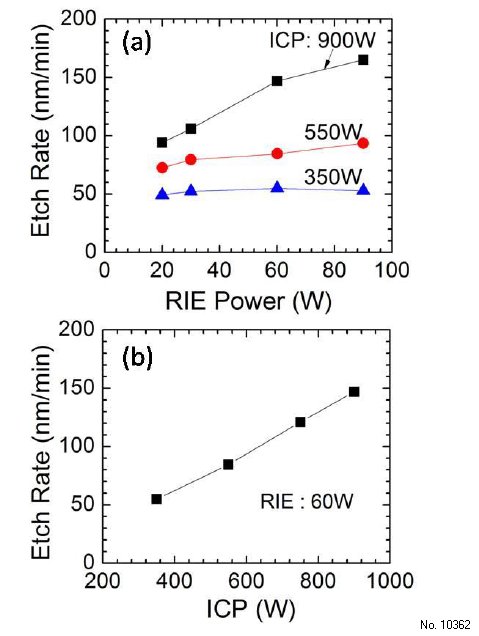
Figure 3.1: (a) Etch rate of UID (-201) ã-Ga2O3 vs RIE power at various ICP powers. (b) Etch rate vs ICP power at 60 W RIE power. All etches have been performed at 5 mTorr chamber pressure and BCl3/Ar flowrates of 35/5 sccm.
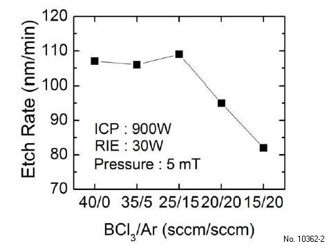
Figure 3.2: Etch rate of UID (-201) ã-Ga2O3 vs BCl3=Ar flow rate at 5 mTorr chamber pressure, 30W RIE and 900 W ICP powers.
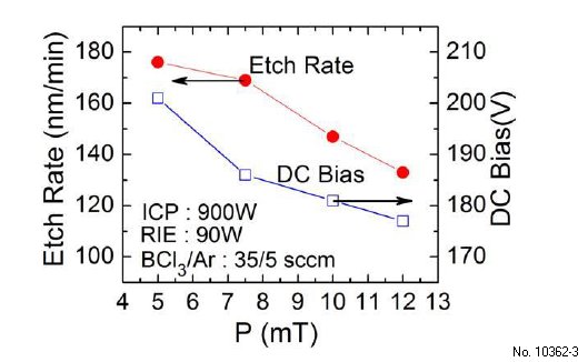
Figure 3.3: Etch rate (left-axis) of UID (-201) beta-Ga2O3 and DC bias voltage (right-axis) vs chamber pressure at 900 W ICP, 90 W RIE, and 35/5 sccm BCl3/Ar flow rate.
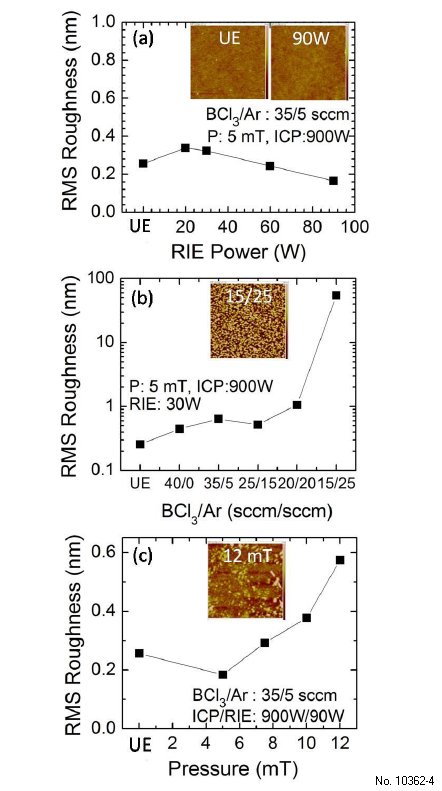
Figure 3.4: (a) RMS roughness of unetched (UE) UID (-201) beta-Ga2O3 sample and samples etched under different RIE powers (inset: AFM image of UE and 90 W RIE sample, height scale bar: +/-2 nm, scan size: 5 x 5 µm2), (b) RMS roughness for UE sample and samples etched with different BCl3/Ar gas flows (inset: AFM image of BCl3/Ar 15/25 sccm sample, height scale bar: +/- 100 nm, scan size: 5 x 5 µm2), (c) RMS roughness for UE sample and samples etched at different chamber pressures (inset: AFM image of 12 mTorr sample, height scale bar: +/- 2 nm, scan size: 5 x 5 µm2).
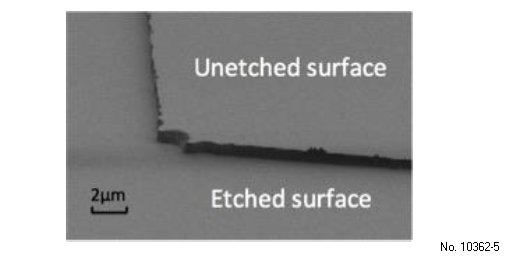
Figure 3.5: SEM image of etched Ga2O3 showing vertical sidewalls and smooth etched surface (ICP/RIE 900W/60W, Chamber pressure 5 mT, BCl3/Ar 35/5 sccm).