Alphabetical Index
Browse by Elements
Keyword Search
Dry Etchants
Dry and Wet Etchants
Wet Etchants
Bulk Etchants
Layer Etchants
Nano Etchants
Single Crystal Etchants
Thin Film Etchants
Thin Foil Etchants
Wafer Etchants
Al Etchants
Cd Etchants
Ga Etchants
Ge Etchants
In Etchants
New Etchants
Other Etchants
Si Etchants
Zn Etchants
Help
Home
Killer Defects Generated in Aluminum Metal Etch Processes
Material Name: Aluminium
Record No.: 10
Primary Chemical Element in Material: Al
Sample Type: Layer
Uses: Etching
Etchant Name: None
Etching Method: Dry etching
Etchant (Electrolyte) Composition: No data
Procedure (Condition): No data
Note:
During metal etch processes (etching aluminum line), Cl2 and
BCl3 are the main reactive gases to etch aluminum. Ar, N2, CF4, CHF3, C2H4, or O2 are also
used during etching and WAC processes. Therefore, the selected chamber materials have to
demonstrate high corrosion (and erosion) resistance to these gases under the high density
plasma. For silicon etch processes, SF6, NF3, HBr and HCl are the main reactive gases used
to etch silicon. Other gases may also be used in the etching and WAC processes. The
selected chamber materials should have a high corrosion resistance to both F-based gases
and HBr corrosion. In particular, the corrosion of HBr mixed with a very tiny amount of
water on the heat effected zone of stainless steel has been an issue for a long time. For
dielectric etching processes, CxFx based reactive gases are usually used with a high applied
power in order to etch oxide. Chamber materials selected have to show high corrosion and
erosion resistance at a relatively high temperature and high power. For special etch
processes such as metal hard mask etch, MRAM etch, high K etch and Bevel etch, special
process gases and chamber conditions are applied. Therefore, the requirements to corrosion
resistance chamber materials may be different. Since some plasma etching processes even
etch noble metals such as Pt, Ru and Ir, one has to find chamber materials which can survive
in these aggressive plasma etching conditions. Therefore, chamber materials which are
submitted to sputtering, chemical etching, ion-enhanced etching, as well as ion-enhanced
inhibitor etching have to be studied and characterized thoroughly for each special etching
applications. There is no any material which can meet all plasma etching applications. In
summary, some of the key requiements of chamber materials is listed below:
- Low erosion rate under vigorous plasma bombardment.
- Low chemical reaction rate under many chemistries such as
- Cl2/BCl3-containing plasma,
- Fluorine-containing plasma,
- HBr/HCl/Cl2-containing plasma,
- Oxygen-containing plasma.
- Low transition metal transport to the workpiece.
- Low or zero particle contamination from surfaces.
- Strong interface bonding of surface coatings for long part lifetime.
- Excellent and repeatable dielectric properties for RF energy coupling.
- Pore-free ceramic materials and low porosity surface coating to avoid undercut corrosion and to eliminate substrate attack.
- Excellent adhesion of etch by-products and polymers.
- Excellent corrosion resistance in wet chemistry cleaning.
- Cost effective in manufacturing.
- Excellent repeatability from part to part and wafer to wafer.
The killer defects which are generated during metal etching processes fall on metal lines and
cause the loss of production yield in wafer fabrication. The killer defects may either come
from chamber materials or etch by-products. For etching process requirement, a metal etch film stack and common issues are shown in
Fig. 1.
The corrosion/erosion patterns of chamber materials showed three different patterns under
plasma. Fig. 3 shows the three different patterns.
Reference: Hong Shih (2012). A Systematic Study and Characterization of Advanced Corrosion Resistance Materials and
Their Applications for Plasma Etching Processes in Semiconductor Silicon Wafer Fabrication, Corrosion
Resistance, Dr Shih (Ed.), ISBN: 978-953-51-0467-4, InTech, Available from: http://www.intechopen.com/books/corrosion-resistance/a-systematic-study-and-characterization-of-advancedcorrosion-
resistance-materials-and-their-applica.

Figure 1: Aluminum metal film stack and common issues in etching processes.
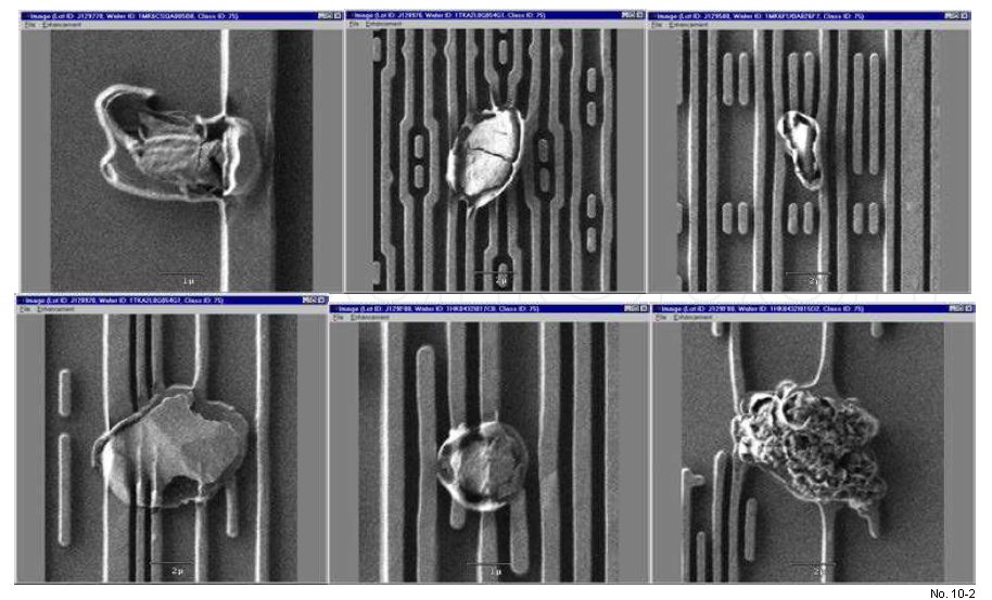
Figure 2: Killer defects generated in aluminum metal etch processes.

Figure 3: Corrosion/erosion patterns of chamber materials under plasma etching (pictures are
at 10,000x magnification). Model A indicates a uniform corrosion/erosion which can either
be higher or low; Model B shows the attack at grains of materials; and Model C shows the
attack at grain boundaries of materials.