Alphabetical Index
Chemical Composition of Steels
Keyword Search
Steel Names
Alloyed Steels
Carbon Steels
Cast Irons
Chromium Steels
Cold Work Tool Steels
Creep Resistant Steels
Hot Work Tool Steels
Molybdenum Steels
PM steels
Stainless Steels
Structural Steels
Tool Steels
Vanadium Steels
White Cast Irons
M2C Carbides
M3C Carbides
M7C3 Carbides
M23C6 Carbides
MC Carbides
Light Microscopy
EDS/WDS Microanalysis
Scanning Electron Microscopy
Transmission Electron Microscopy
X-Ray Diffraction
Help
Contact Us
Home
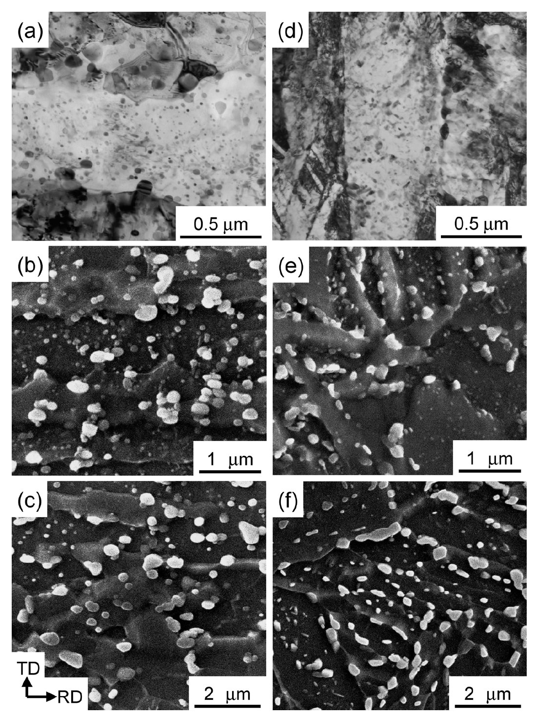
Carbides in 0.57C-1.96Si-0.16Mn-1.02Cr steel

Figure 1: Carbide microstructures of the samples that were tempformed
at 500 (a), 600 (b) and 700°C (c) and were conventionally
quenched and tempered at 500 (d), 600 (e)
and 700°C (f). Scale bars: 0.5, 1, 2 µm.
Carbide name: No data
Record No.: 1077
Carbide formula: No data
Carbide type: No data
Carbide composition in weight %: No data
Image type: SEM, TEM
Steel name: 0.57C-1.96Si-0.16Mn-1.02Cr
Mat.No. (Wr.Nr.) designation: No data
DIN designation: No data
AISI/SAE/ASTM designation: No data
Other designation: No data
Steel group: Structural steels
Steel composition in weight %: 0.57% C, 1.96% Si, 0.16% Mn, 0.001% P, 0.001% S, 0.041% Al, 1.02% Cr, 0.002% Mo, 0.0018% N, 0.0005% O.
Heat treatment/condition: A 100 kg ingot was prepared by vacuum melting and casting, homoghomogenized
at 1200°C, and then hot-rolled to a plate with a
thickness of 4 cm. A 12 by 4 by 4 cm block was cut out of
the plate, heated to 1200°C, hot-rolled to a square bar with
a cross section area of 10 cm2, solution-treated at 1200°C
for 60 min, and water quenched to obtain a martensitic
structure without any coarse undissolved carbides. The average
prior-austenite grain size of the quenched bars was
210m m and the hardness was HV 850. The quenched bars
were tempered at 500, 600 and 700°C for 90 min, subjected
to multi-pass caliber-rolling at the respective temperatures
to square bars with a cross section area of 2 cm2, and air
cooled (tempformed (TF) samples). The accumulative reduction
in area through tempforming was 80% in ten
passes, which corresponds to an equivalent strain of 1.8.
Note that the samples were held for 5 min in a furnace after
every three passes during the rolling and passed through
twice for the final groove to control the cross sectional
shape of the bars, namely the pass schedule was 3-3-4 at
each temperature. To obtain conventional quenched and
tempered samples with the same tensile strengths for comparison,
normalized bars were austenitized at 880°C for 30
min, followed by oil quenching, tempered at 500, 600 and
700°C for 90 min, and then water cooled (QT samples).
The QT samples had an average prior-austenite grain size
of 26 µm and showed random textures.
Note: The deformation of tempered martensitic structures, namely tempforming treatments, were applied to a
0.6C–2Si–1Cr steel at 500, 600 and 700°C using multi-pass caliber-rolling with an accumulated area reduction
of 80%. The tensile and Charpy impact properties were investigated to make clear the relation between
the microstructure and the delamination behavior of the tempformed (TF) samples. The tempforming treatments
resulted in the evolution of ultrafine grain structures with strong <110>//rolling direction (RD) fiber deformation
textures and fine spheroidized cementite particles distributions. In contrast to the ductile-to-brittle
transition of the conventional quenched and tempered (QT) samples, the TF samples exhibited inverse temperature
dependences of the impact toughness due to the delaminations, where the cracks branched in the
longitudinal direction (//RD) of the impact test bars. As a result, high strength with excellent toughness was
achieved in the TF samples. A yield strength of 1364 MPa and a V-notch Charpy absorbed energy of 125 J
were obtained at room temperature in the sample that was tempformed at 500°C. The delamination was
shown to occur due to the microstructural anisotropy of the TF samples, and the dominating factors controlling
the delamination toughening were the transverse grain size, the grain shape and the .110.//RD fiber deformation
texture. The discussion also indicated that the ultra refinement of the transverse grain structure
was the key to enhancing both the yield strength and the toughness of the TF steel while lowering the ductile-
to-brittle transition temperature.
Figure 1 are TEM and SEM images showing morphologies
and distributions of carbide particles of the TF and QT
samples. Spheroidized cementite particles are dispersed in
all of the TF samples. Relatively large cementite particles
exist on the (sub) boundaries of the matrix ferrite grains,
while finer spherical cementite particles are homogeneously
dispersed inside the matrix grains. In particular, the cementite
particles on the (sub) boundaries may play an important
role in retarding the grain migration through their pinning
effect during tempering and tempforming. The average aspect
ratios of cementite particles were measured to be about
1.3 inside the grains and 1.5 on the (sub) grain boundaries, respectively. The average lengths of the long axis for the cementite
particles inside the grains and on the (sub) boundaries
in tempforming at 500°C are 28 and 64 nm, respectively,
and increased to 177 and 370 nm in tempforming at
700°C. It appears that the number of cementite particles inside
the grains tends to decrease with increasing tempforming
temperature. When compared at the same tempering
temperature, there is no significant difference in the cementite
particle size distribution between the QT and TF samples.
This indicates that such bimodal distributions for the
cementite particles in the TF samples might be inherited
from those of prior tempered martensitic structures.
Links: No data
Reference: Not shown in this demo version.