Alphabetical Index
Chemical Composition of Steels
Keyword Search
Steel Names
Alloyed Steels
Carbon Steels
Cast Irons
Chromium Steels
Cold Work Tool Steels
Creep Resistant Steels
Hot Work Tool Steels
Molybdenum Steels
PM steels
Stainless Steels
Structural Steels
Tool Steels
Vanadium Steels
White Cast Irons
M2C Carbides
M3C Carbides
M7C3 Carbides
M23C6 Carbides
MC Carbides
Light Microscopy
EDS/WDS Microanalysis
Scanning Electron Microscopy
Transmission Electron Microscopy
X-Ray Diffraction
Help
Contact Us
Home
Cementite particles in AISI 1045 steel

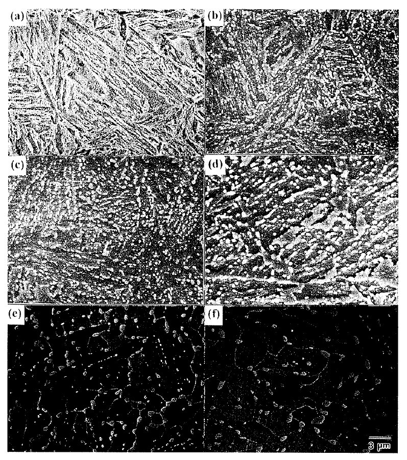
Figure 1: The changes in the distribution of cementite particles for different tempering time at 973 K in martensite.
(a) quenched (b) 5 min(c) 30 min (d) 2 hr (e) 10 hr (f) 50 hr. Scale bar: 3 µm.

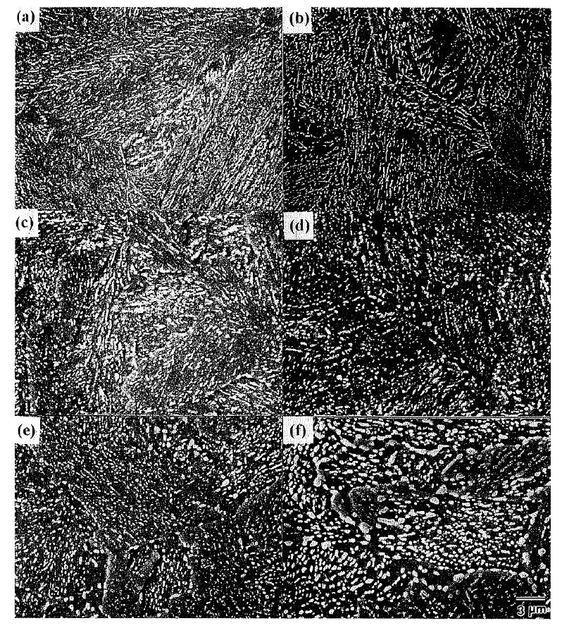
Figure 2: The coarsenining behaviors of cementite particles for different tempering time at 973 K in bainite.
(a) quenched (b) 5min (c) 30 min (d) 2 hr (e) lO hr (f) 50 hr. Scale bar: 3 µm.

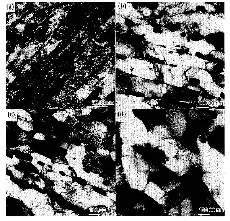
Figure 3: The chtmges in the matrix in martensite during tempering at 973 K.
(a) quenched (b) 30min (c) 2 hr (d) 10 hr. Scale bars: 50, 100 nm.

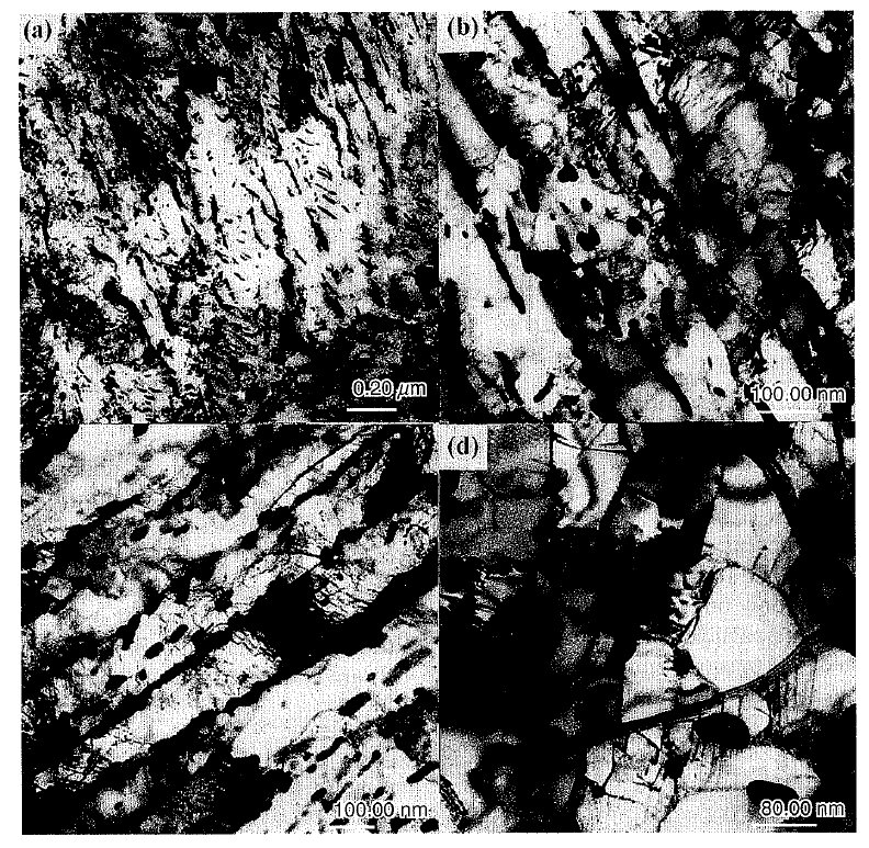
Figure 4: The changes of bainitic microstructure during tempering at 973 K.
(a) quenched (b) 30 min (c) 2 hr (d) 10 hr. Scale bars: 20, 80, 100 nm.
Carbide name: Cementite
Record No.: 1092
Carbide formula: Fe3C
Carbide type: M3C
Carbide composition in weight %: No data
Image type: SEM, TEM
Steel name: AISI 1045
Mat.No. (Wr.Nr.) designation: No data
DIN designation: No data
AISI/SAE/ASTM designation: AISI 1045
Other designation: No data
Steel group: Medium carbon steels
Steel composition in weight %: 0.45% C, 0.22% Si, O.62% Mn, 0.004% P, O.0038% S.
Heat treatment/condition: To produce the different initial
microstructures, the rods with lO mm diameter were
austenitized at 1173K for 30 min followed by quenching
to water or the salt bath with the temperature of
653K for 1 hr. For temperlng treatments, the heating
rate was lO C/min, and heating temperature was 973 K.
By varying holding time at 973 K, the samples were
quenched into water to investigate the coarsening behavior
of cementite particles.
Note: The effect of initial microstructures, martensite and bainite, on the coarsening behavior of cementite
particles during tempering at 973K for medium carbon steels has been investigated. The coarsening of
cementite particles in bainite proceeded more slowly than in martensite, due to the thermal stability of
cementite particles in bainite. The coarsening of cementite particles proceeded by a combination of the
different coarsening mechanisms. The observed coarsening kinetics in martensite were found as acombination
of boundary diffusion and diffusion along dislocation for cementite particles at boundaries, and a combination
of boundary diffusion and matrix diffusion for cementite particles within laths. In bainite, the coarsening
was controlled by a combination of boundary diffusion and diffusion along dislocation for intergranular
particles, and controlled mainly by diffusion along dislocation for intragranular particles.
Figure 1 shows the changes in the distribution of
cementite particles during tempering at 973 K. Characteristic
features after short tempering time less than 2 hr (Figs. 1(b)-1(d)) are the appearanceof elongated regions
which are almost denuded of cementite partlcles. The similar shape and size of the denudedareas in Fig, l(b),
tempered for 5 min, to that of martensite needles in Fig.
l(a), indicate that cementite particles are preferentially
located at the martensite needle boundaries and that the
denuded areas are associated with needles. At the very
beginning of tempering martensite, the nucleation of
cementite starts with the concurrent eiimination of
epsilon-carbide within martensite laths, retained austenite
decomposesin to ferrite and cementite at lath or prior
austenite boundaries. Particles at boundaries have the
lower interfacial energy than equivalent sized particles
in the matrix. Since the dissolution of smaller particles
within martensite laths occurs due to the solute diffusion
from the matrix to boundaries, the number of
intragranular particles would decrease with the progress
of spheroidization and coarsening. Consequently, the
coarsening of cementite particles proceeds by the growth
of large cementlte particles at boundaries with the
dissolution of smaller particles within martensite laths
and results in the formation of the denuded areas.
Further increment of tempering tlme up to 2 hr (Figs. l(c)-1(d)) shows the increase of the size of denuded
areas, although they still retain the elongated shape, as
well as the slze of cementite particles at boundaries. The
observed non uniformity in the particle size maybe due to an initial growth of boundary particles during the
early stage of tempering. In addition, small boundary
particles may dissolve and allow grain boundary diffusion
to favor the growth of larger neighbors during
tempering. Accordingly, cementite partlcles at boundaris
are always larger than intragranular particles.
After lO hr tempering (Fig. 1(e)), the presence of
equiaxed ferrite grains is observed and most cementite
particles are located at ferrite boundaries. A few cementite
particles remainlng inside ferrlte grains would
come from the result of the migration of ferrite grain
boundaries during grain growth. Longer temperlng time
of 50 hr, Fig. l(f), produces little change in the
microstructure, except for the growth of ferrite grains
and cementite particles.
The coarsening behavior of cementite particles in
bainite at 973 K in Fig. 2 is different from that in
martensite. Since the transformation of austenite into
bainite occurs at relatlvely high temperatures, cementite
particles tend to be coarser and more thermally stable
than those associated with tempered martensite. Furthermore,
since most cementite particles with the similar
size are located at lath boundaries, lath boundaries, or
prior austenite boundaries, the reduction of concentration
gradients of solute atom would slow down the coarsening behavior of cementite particles during tempering.
Accordingly, unlike martensite there has been little
change in the distribution and size of cementite particles
up to tempering tirne of 2 hr (Fig. 2(b)-2(d)), although
the size of cementite particles located at boundaries are
slightly larger than those located inside. The only
difference detected in the micorgraphs is the change In
the morphoiogy of cementite particles from initially
rod-shaped to rather spheroid-shaped. Consequently,
only mlnor changes in the morphology of cementite
particles are observed. Thus, it can be said that bainitic
mlcrostructures are muchless sensitive to tempering.
However, after lOvhr tempering (Fig. 2(e)), the nonuniformity
in the dlstribution and size of cementite
particles, which is associated with the coarsening of
cementite particles, can be observed. This morphology
maybe due either to the growth of larger neighboring
particles at boundaries with the dissolution of smaller
boundary particles, or to boundary plnning being more
effectlve for large particles durlng tempering. When
tempering time incre'ases up to 50 hr (Fig. 2(f)), this
difference becomes more evident. The microstructure
consists of mainly coarse cementite particles located at
feerrite boundaries, and fine particles inside boundaries.
The changes in the matrix structure have an influence
on coarsening behavior of cementite particles during
tempering of martensite. After 30 min tempering the
substructure in the elongated form is well developed and
all cementite particles are associated with subboundaries
or dislocations, as shown in Fig. 3(b). Although, in the
present investigation, a quantitative analysis regarding
the effect of tempering time on the substructure size
and the dislocation density has not been performed, the
apparent increase of the substructure width and decrease
of dislocation density from martensite in Fig. 3(a),
indicate that the polygonization and the annihilation of
dislocations are operative as a recovery process. As
tempering proceeds up to 2 hr (Fig. 3(c)), the presence
of more equiaxed subgrains is detected, although the
stringers of cementite particles are still remained. For
longer tempering time of 10 hr in Fig. 3(d), the microstructures
are similar to those observed in Fig. 3(c),
except for the growth of subgrains, the more randomly
distributed and large sized cementite particles.
Figure 4 shows the changes of bainitic microstructure
during tempering at 973 K. When tempered for 30 min
in Fig. 4(b), the well developed substructure in the
elongated form indicates the progress of recovery. All
the observed cementite particles, which are either rod shaped
or spheroid-shaped, are located at subboundaries
or dislocations. However, unlike martensite, most
particles observed in Fig. 4(b) shows the little variatlon
in the size and the width of the substructure is much narrower than those observed in martensite (Fig.
3(b)). This implies that the higher thermal stability and
fine distribution of cementite particles in bainite would
effectively hinder the movementof dislocations and
slow downthe polygonizatlon and the annihilation of
dislocations during recovery.
When tempering time increases up to 2 hr (Fig. 4(c)),
any noticeable change in the microstructures, such as the
size of cementite particles and the shape of substructures
is not detected. Only the changes observed in Fig. 4(c)
are the shape of cementite particles from the rod-type to
spheroid-type, although they still exist as the stringers
of particles, and the increase of the width of substructure.
For longer tempering time of 10 hr in Fig. 4(d), the
presence of equiaxed subgrains can be detected and the
size of cementite particles connected with subboundaries
Is increased. Although the general features are similar to
those observed in Fig. 3(d), the size of subgrains and
cementite particles are smaller than those in martensite.
Links: No data
Reference: Not shown in this demo version.