
Alphabetical Index
Chemical Composition of Steels
Keyword Search
Steel Names
Alloyed Steels
Carbon Steels
Cast Irons
Chromium Steels
Cold Work Tool Steels
Creep Resistant Steels
Hot Work Tool Steels
Molybdenum Steels
PM steels
Stainless Steels
Structural Steels
Tool Steels
Vanadium Steels
White Cast Irons
M2C Carbides
M3C Carbides
M7C3 Carbides
M23C6 Carbides
MC Carbides
Light Microscopy
EDS/WDS Microanalysis
Scanning Electron Microscopy
Transmission Electron Microscopy
X-Ray Diffraction
Help
Contact Us
Home
Fe3C, VC, M7C3 and M23C6 carbides in heat resistant 12Kh1MF steel
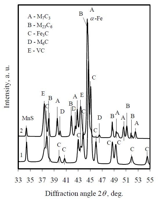
Figure 1: X-ray diffraction patterns of 12Kh1MF virgin (curve 1)
steel and exploited 227000 h at 550 °C temperature and
pressure of 14 MPa (curve 2).
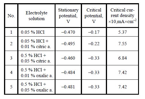
Table 1: Electrochemical parameters of 12Kh1MF steel in electrolytes solutions.
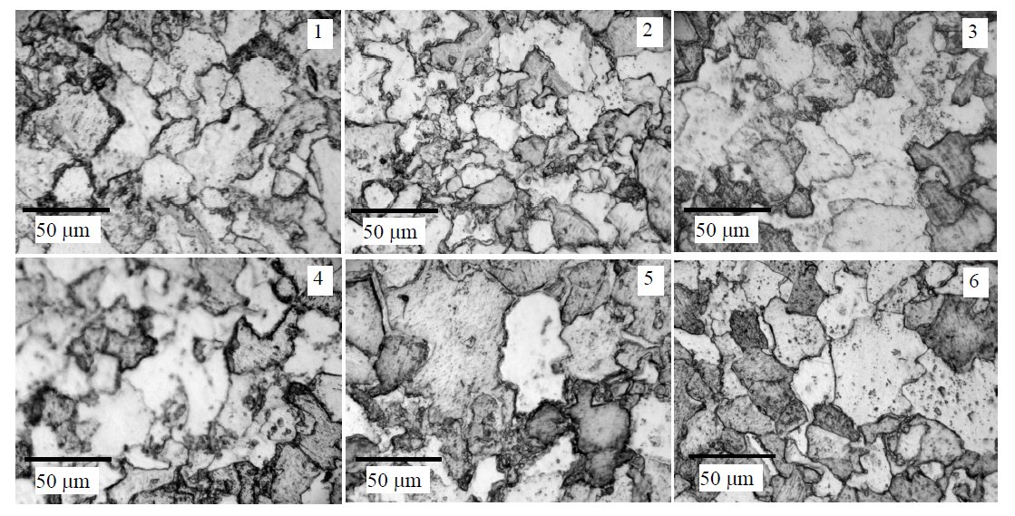
Figure 2: Optical microstructure of 12Kh1MF steel tempered at 700 °C (hours) and etched by 10 % ferrous (III) chloride solution:
1 – virgin steel, 2 – 24, 3 – 48, 4 – 144, 5 – 384 hours, 6 – exploited 227000 hours at 550 °C. Scale bars: 50 µm.

Figure 3: Microstructure (SEM) of 12Kh1MF steel tempered at 700 °C: 1 – virgin state, ferrite-pearlite; 2 – 384 h heated, partial
disintegration of pearlitic structure; 3 – 227000 h exploited at 550 °C, full disintegration of pearlitic structure. Scale bars: 5 µm.
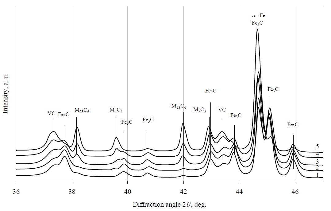
Figure 4: X-ray diffraction patterns of 12Kh1MF steel tempered at 600 °C. Curves: 1 – virgin steel, 2 – 48 h, 3 – 216 h, 4 – 384 h, 5 – 854 h.
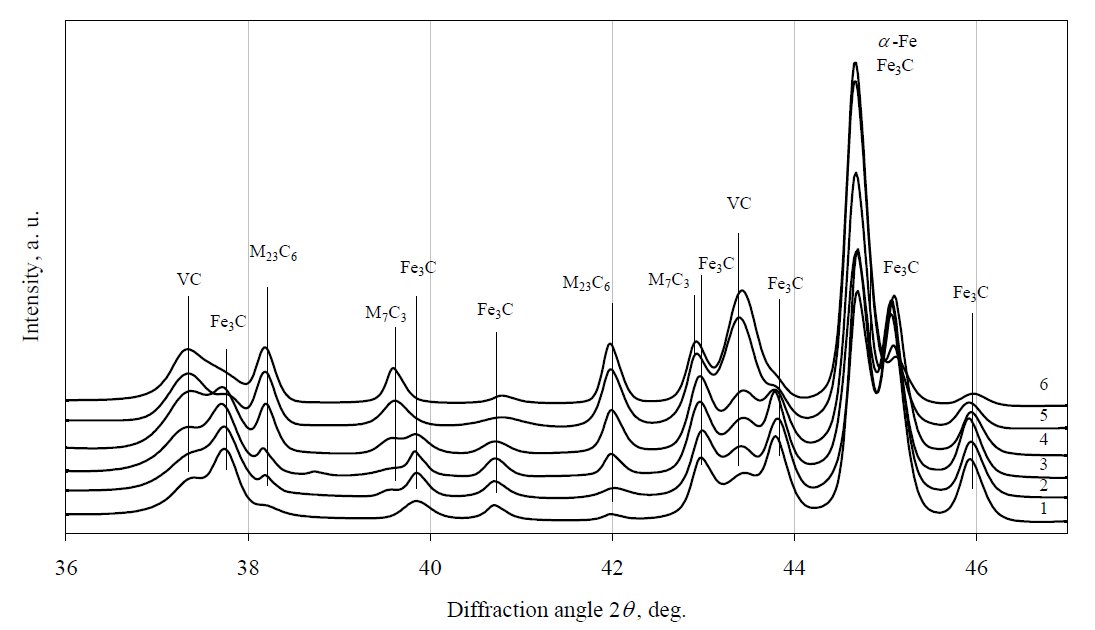
Figure 5: X-ray diffraction patterns of 12Kh1MF steel tempered at 650 °C. Curves: 1 – virgin steel, 2 – 24 h, 3 – 192 h, 4 – 288 h,
5 – 384 h, 6 – 854 h.
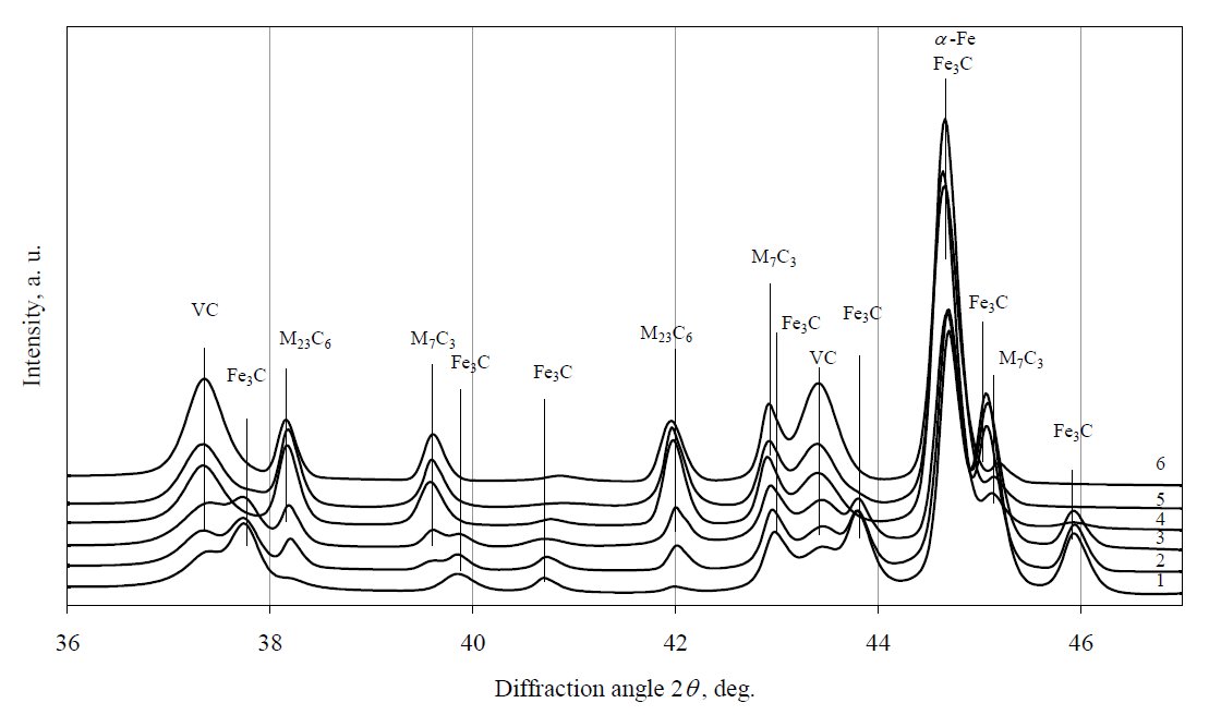
Figure 6: X-ray diffraction patterns of 12Kh1MF steel tempered at 700 °C. Curves: 1 – virgin steel, 2 – 24 h, 3 – 48 h, 4 – 192 h, 5 – 384 h,
6 – 576 h.
Carbide name: Fe3C, VC, M7C3, M23C6
Record No.: 849
Carbide formula: Fe3C, VC, M7C3, M23C6
Carbide type: M3C, MC, M7C3, M23C6
Carbide composition in weight %: No data
Image type: SEM, XRD
Steel name: 12Kh1MF
Mat.No. (Wr.Nr.) designation: No data
DIN designation: No data
AISI/SAE/ASTM designation: ASTM: F12C1.1
Other designation: EN: 13CrMo4-5
Steel group: Heat resistant steels
Steel composition in weight %: 0.12% C, 1.1% Cr, 0.54% Mn, 0.26% Mo, 0.26% Si, 0.17% V, 0.019% S, 0.015% P.
Heat treatment/condition: Investigated 12X1M. steel was taken from a thick
section of superheated steam pipes originally supplied by
SC “Lietuvos elektrine”. The samples were prepared from
virgin and exploited for 227000 h at 14 MPa pressure and
550 °C – 560 °C steel. Using a potentiostat PI-50-1 and a
programmer PER-8 steel anodic polarization curves
(e. g. dependence of operating electrode potential on
current density) were recorded in solutions of different
electrolytes, electrochemical etching solutions and the
parameters (critical current density, critical potential) were
determined.
The samples (60 mm × 20 mm × 20 mm, working area
2.2 cm2 ÷ 2.5 cm2) of 12X1M. steel were soaked into 20 °C electrolyte solution and current measurements were
carried out according argentums chloride reference electrode
(EVL – 1M3.1), when the sample potential from the
stationary value to 1.2 V varied at 1·10–3 V/s or 5·10–3 V/s
rate. Performing anodic polarization of heat resistant steel,
Fe ions, which forms insoluble bivalent and then trivalent
ferrous hydroxides (Fe(OH)2, Fe(OH)3), enter the electrolyte
solution. Anodic polarization curves were recorded in 0.05 %
and 0.5 % hydrochloric acid solution and in hydrochloric
solution with 0.01 % and 0.05 % oxalic or citric acid
concentrations.
Note: Parameters of carbide phase electrochemical separation in electrolytes solutions of pearlitic 12Kh1MF heat resistant
steel, used in thermal power plants facilities are presented in the article. The most relevant electrolyte is chosen and its
concentration is specified. Operated and under laboratory conditions aged steel surface microstructure and morphology
were evaluated by optic and scanning electron microscopy methods. Using electrochemical etching and XRD qualitative
analysis of carbide compounds of 550 °C exploited steel and aged under laboratory conditions at 600, 650, 700 °C from
24 h up to 864 h was carried out. Kinetics of carbides formation is given in mathematical equations. It was determined
that during exploitation and ageing samples at 700 °C for 576 h the steel pearlite completely decomposes, whereas alloy
elements diffuse into intergrain area thus forming special alloy carbides. Experiments revealed that the XRD analysis of
electrochemically separated carbide phase is a rapid and informative method of evaluation the service condition of steel.
The initial microstructure of power plant alloy 12Kh1MF consists of ferrite-pearlite or
ferrite-bainite as the major phases obtained following a
hardening and normalizing heat treatment later on subjected
to very severe tempering (~650 °C…700 °C for
several hours) generating the overall coarsening and the
precipitation of ever more stable alloy carbides and
intermetallic compounds (Fig. 1, curve 1), witch interfere
with the progress of dislocations. These solid state
reactions eventually determine the properties and
mechanical stability of the power plant steels (for example,
the resistance to creep deformation) and their useful design
lifetimes.
In the heat and power generating plants, the pipelines
are used to transport superheated steam in the temperature
range 500 °C – 560 °C and under a pressure,
P = 10 MPa – 15 MPa. During long time service in creep
regime to such conditions the microstructure of steel
changes, pearlite/bainite decomposes as well as carbides
precipitation at the grain boundaries and carbides coarsening
processes proceed (Fig. 1, curve 2). Structure changes
cause formation of cavities and development of internal
damages. It is well known that there is a close coherence
between changes in microstructure and deterioration
of mechanical properties, however, the accurate relation for creep rupture strength deterioration regarding the
microstructural degradation is not yet determined.
Microstructure changes of 12Kh1MF steel surface
during its ageing were observed using optic microscopy
and scanning electron microscopy methods. In optical microscopy photos (Fig. 2, picture 1) of
untreated steel pearlite and ferrite grains are observed,
however it is hard to identify fine carbide compositions.
High temperature ferrite and pearlite grains begin to decompose and in their limits the chains (Fig. 3, pictures
2 – 6) of alloyed carbides are formed, which are difficult to
see in pictures since both the resolution, depth of field and
range of magnifications (to about 550×) of the light
microscope are not sufficient.
The ongoing structure changes of samples and
nucleation of voids may be analysed in an objective way
with the scanning electron microscope. In SEM pictures
(Fig. 3) the steel ferrite-pearlite structure can be clearly
seen. After treating the sample for 384 h at 700 °C, the
pearlitic structure partially decomposes (Fig. 4, picture 2),
whereas in the photo of the sample treated for 227000 h at
550 °C, a full disintegration of pearlitic structure (Fig. 3,
picture 3) is recorded.
XRD analysis was used to confirm carbides formation
in steels during their ageing as well as to perform kinetics
research. According to the steel critical current density,
determined by anodic polarization method, steel etching
operating current density was chosen. Its value corresponds
to approximately half critical current density. Since
for real samples due to approximately 10 times bigger
surface area the analysed 0.05 % electrolyte concentration
was too small (steel solution process ended very quickly,
when a sufficient amount of carbide phase had not yet been
released), it was increased up to 5 %.
Fig. 4 shows X-ray diffraction patterns of electrolytically
extracted residues of specimens during the early stages of
tempering at 600 °C. After 48 h tempering exposure, intensity
of diffraction peaks of Fe3C, VC and traces of M23C6 (M
stands for metals: iron, chromium, molybdenum and vanadium)
remains almost unchanged but small amount of M7C3
has been detected (Fig. 4, curve 2). After 216 h accelerated
ageing the diffraction peak of carbide M23C6 considerably
increases (Fig. 4, curve 3) while Fe3C diffraction peak
marginally diminishes. The most significant changes have
been identified after 654 h isothermal ageing (Fig. 4, curve 5).
The intensity of M23C6, VC and M7C3 diffraction peaks
considerably increase, while Fe3C significantly decreases. All
the data showed that tempering causes the Fe-rich M3C
carbide (the kinetically favoured phase in the pearlite) to
transform to more thermodynamically favoured carbides,
rich in Cr and Mo. The most thermodynamically stable
carbide M6C was not yet identified.
After further performing XRD analysis of the samples,
it was determined that during ageing of 12Kh1MF steel at
650 °C and 700 °C (Fig. 5 and Fig. 6), the concentration of
Fe3C reduces more rapidly and, at the same time, the rate of transformation to M23C6 alloy carbide is accelerated. No
precipitation of stable carbide M6C was detected too. So,
the same carbide precipitation sequence was observed at
650 °C and 700 °C as it was detected at 600 °C, although
the precipitation kinetics appears to be faster for all phases
at that temperatures. Because the carbide M6C have been
detected in 12Kh1MF steel exploited for 227000 h, thus it
would be meaningful to continue experiments at elevated
temperatures to obtain conditions of full carbide
precipitation sequence. These results would be useful for
evaluation of steel service time and for prediction remnant
life.
Links: No data
Reference: Not shown in this demo version.